SWITCHPATH LIGHTS™
KEEP SCROLLING DOWN TO EXPLORE MORE
Simplified Alignment Indication
There is no system on the market that makes it this easy to understand switch alignment. GUARANTEED
The fundamental principle differentiating SwitchPath Lights™ from ALL other switch position indicators is the instant understanding of which track is safe to travel. There is ZERO interpretation required. The track with the flashing lights is the safe track. ALL other switch position indicators require one or more mental steps to decipher switch alignment. For example 1) Does the white target on the stand represent straight or divergent alignment? 2) Which track am I on? and 3) Do these answers match to let me know travel on current track is safe? SwitchPath Lights™ require one question to be answered, “Are there lights blinking in front of me or the other track?”
Reliable Solar Power

360° Viewing Angle
From a conductor’s perspective: When a train is sitting on or close to points and blocking visual confirmation of a stand target, SwitchPath Lights™ can still be seen to inform alignment of switch. This is the only switch position indicator on the market that can be seen facing away from the points.
The Point Sensor
The SwitchPath Lights™ point sensor is mounted near the front of the points and utilizes a spring loaded stainless steel rod, to detect the position of the points. That information is relayed through heavy duty cables to each of the LED lights. This sensor is also available for sale as a stand alone component for projects requiring switch position detection.
The LED Lights
SwitchPath Lights™ provides illumination using a series of 5 LED lights, 1 of which is shared between the two tracks and two on each of the straight and divergent tracks. Each LED light is housed in a rugged aluminum housing and sealed to ensure they are not affected by rain or temperature. The housings can be mounted to wood, concrete, composite, or steel ties and easily removed if needed.
The Wires
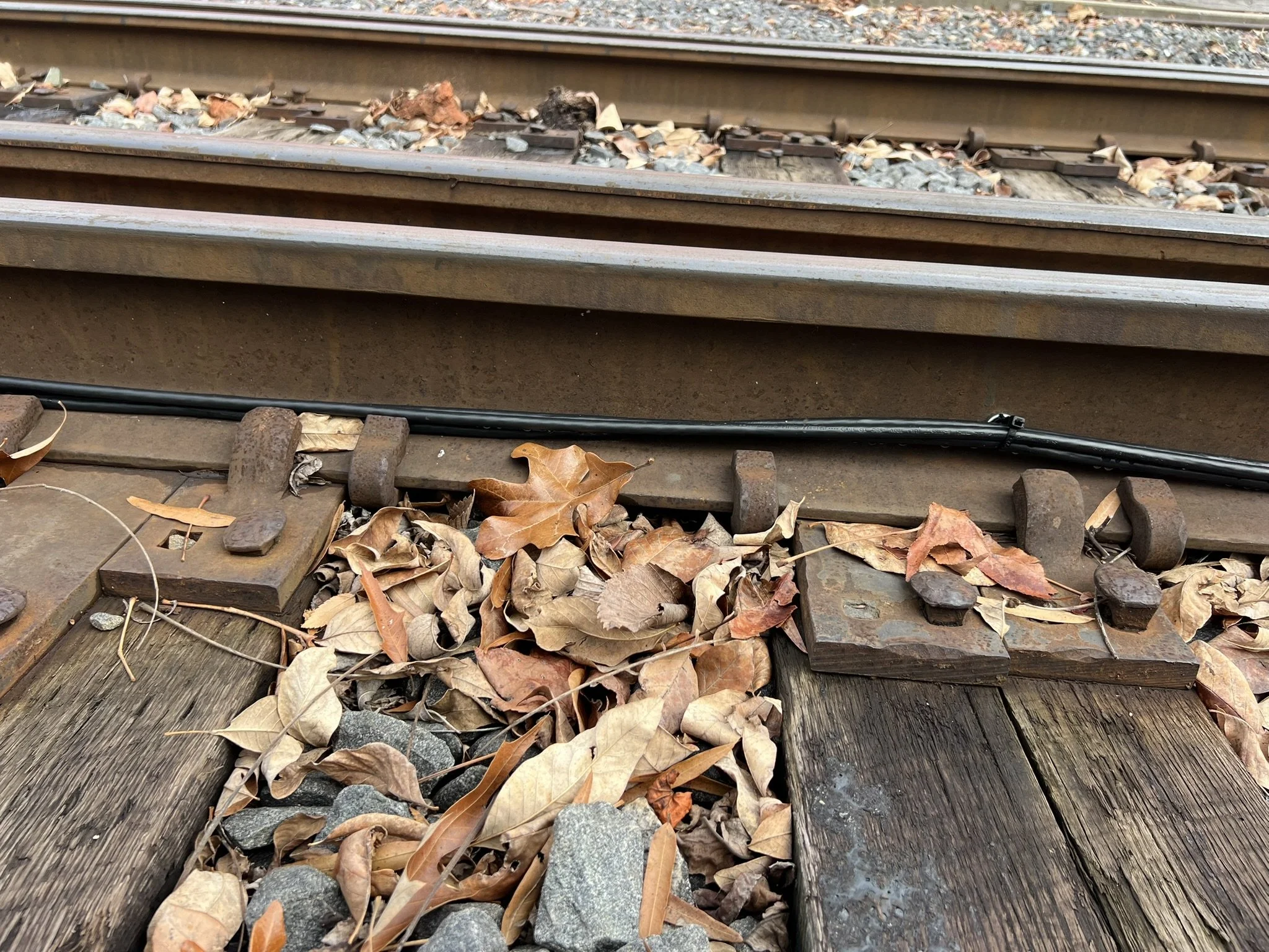

SwitchPath Lights™ uses a series of heavy-duty wiring to connect the power source, point sensor, and LED lights. To ensure these wires presented no tripping hazard, considerable time was devoted to designing a wiring layout that allowed for safe foot traffic and zero interference with train components. Additionally, we wanted to ensure the majority of rail repairs could be completed without having to move the wires or other system components. The above images show a side view of the wires being held in place within the web of a rail, an overhead view showing there is no interference in the footpath at the end of the tie, as well as two videos showing spikes being pulled and driven down for a small re-gauging job. For jobs requiring a regulator, we provide a step by step guide for disconnecting and reconnecting the system, which takes about and 30 minutes.